|
National Aeronautics and Space Administration Goddard Space Flight Center |
SEARCH NASA |

 MOLA MOLA |
*Zuber, M.T., D.E. Smith, S.C. Solomon, J.B. Abshire, R.S. Afzal, O. Aharonson, K. Fishbaugh, P.G. Ford, H.V. Frey, J.B. Garvin, J.W. Head, A.B. Ivanov, C.L. Johnson, D.O. Muhleman, G.A. Neumann, G.H. Pettengill, R.J. Phillips, X. Sun, H.J. Zwally, W.B. Banerdt, T.C. Duxbury, Observations of the north polar region of Mars from the Mars Orbiter Laser Altimeter, Science, 282,, 2053-2060, 1998.
Download a PDF version of the paper.
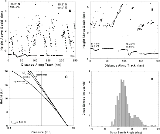
Figure 1. Polar stereographic projections from 55° N to the Martian north pole. (A) MOLA coverage during the MGS science contingency and aerobraking hiatus orbits (in blue: AHO; September-November 1997, orbital period = 37 - 41 hours), and Science Phasing Orbits (in green: SPO-1, March-April 1998, and in red: SPO-2, June-July 1998, both with orbital period = 11.6 hours). (B) Geologic map of the Martian north polar region after Tanaka and Scott [1987]. Apl - polar layered terrain; Api - polar ice; Am - polar mantle material; Adc - crescentic dunes; Adl - linear dunes; Hv - mantled plains; c - cratered terrain. (C) Relief-shaded plot of topography relative to the geoid, interpolated to 2-km spatial resolution. (Credit: MOLA Science Team)

Figure 2. Perpendicular profiles across the north pole of Mars sampled at the stated longitudes from a 2-km grid of MOLA elevations. Note that the north polar region represents a hemispheric minimum in elevation. The Tharsis rise is the topographic high at the right of the top profile. (Credit: MOLA Science Team)
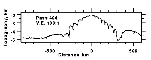
Figure 3. Pass 404, which crossed directly over the north pole, shows that the polar cap has a maximum elevation of about 3 km above its surroundings. (Credit: MOLA Science Team)

Figure 4. Polar projection of MOLA topography between 75° N and the north pole interpolated to 1-km spatial resolution. The contour interval is 100 m. The absolute accuracy of grid points with respect to Mars' center of mass ranges from 5-30 m. (Credit: MOLA Science Team)
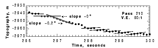
Figure 5. Pass 210 shows 4 s of data centered at 85.7° N, 4.0° E, corresponding to a 15-km distance along the MGS spacecraft groundtrack. The shot spacing is 400 m. Grey lines show that the maximum along-track slope is 0.2° and the minimum slope is statistically indistinguishable from 0 over a 1.6 km baseline. This profile demonstrates that over smooth surfaces the instrument is performing at its 37.5 cm range resolution. (Credit: MOLA Science Team)
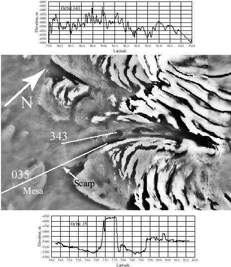
Figure 6. Viking image mosaic of Chasma Boreale showing MOLA elevations along Passes 35 and 343. Pass 343 shows a scarp at mouth of Chasma Boreale on left (S) end of profile and a basin (filled with dark dune material) on the right (N) end. Pass 35 shows scarp and an outlier mesa and crosses an impact crater on the mesa. (Credit: MOLA Science Team)
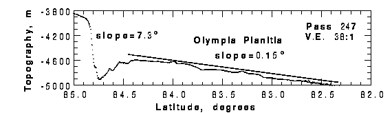
Figure 7. Pass 247 shows a topographic profile across the residual cap (at left) and Olympia Planitia. (Credit: MOLA Science Team)

Figure 8. (A) Viking image 65B58 (resolution 52 m/pixel) of a ~30-km-diameter ice-filled impact crater at 77° N, 215° E. Shown are the MGS groundtrack and MOLA elevations along Pass 415. (B) Cross-sectional view of profile with MOLA elevations and shot-to-shot surface slopes (plus symbols), plotted vs. latitude. The parabolic line is the reconstructed crater cavity based upon MOLA observations of non-polar craters [J.B. Garvin and J.J. Frawley, Geophys. Res. Lett., 25, 4405-4405, 1998]. (Credit: MOLA Science Team)